← Home · Ground improvement

Vibrocompaction Design for Florida's Karst and Sandy Soils

Together, we solve the challenges of tomorrow.

DISCOVER →

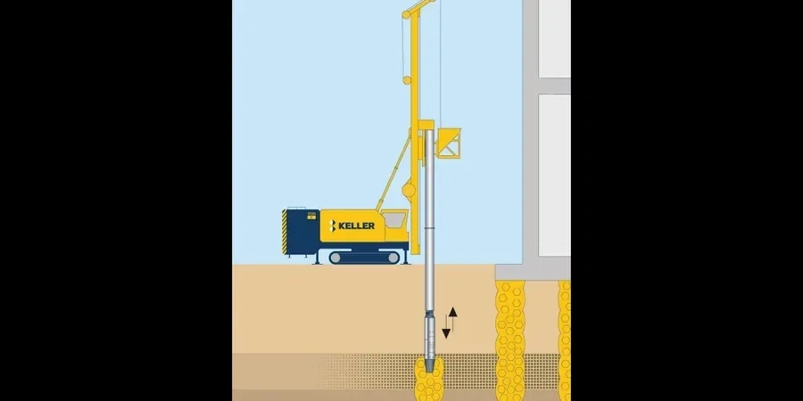
Orlando's subsurface profile creates specific challenges that the IBC and ASCE 7 address through strict ground improvement standards. Many sites across the city sit on loose to medium-dense sands with occasional silty lenses, and the water table is often just a few feet below grade. We design vibrocompaction layouts that densify these granular deposits and reduce the risk of differential settlement under structural loads. Our approach integrates field data from spt-drilling to calibrate target relative density, and we verify particle distribution with grain-size analysis before finalizing the probe grid. Each design accounts for the city's humid subtropical climate, where seasonal rainfall can temporarily raise the groundwater and alter compaction efficiency during construction.

Targeting 70 percent relative density after vibrocompaction transforms loose Orlando sands into a reliable bearing stratum without importing fill.

Method and coverage

One condition our laboratory team consistently observes in Orlando is the presence of thin organic layers interbedded with clean sands, particularly near the city's numerous lakes and former wetland areas. These layers do not respond to vibratory energy the way clean quartz sand does, so the design must identify their extent and either bypass them or combine vibrocompaction with localized over-excavation. We typically specify probe spacing between 6 and 10 feet in a triangular grid, adjusting the pattern based on CPT tip resistance and SPT blow counts collected before the trial program. The design also includes a performance specification: a minimum relative density of 70 percent across the treatment zone, verified with post-compaction cpt-test soundings at offset locations. For sites within the Orange County sinkhole activity zone, we add a deeper investigation component to confirm that loose soils are not bridging incipient karst features below the treatment depth.
Vibrocompaction Design for Florida's Karst and Sandy Soils
Technical reference image — Orlando

Regional considerations

Orlando recorded over 80 sinkhole incidents in a single year during the 1990s, and while most were small, the karst limestone beneath the city means that loose overburden can migrate downward without warning. Designing vibrocompaction in this setting calls for caution: the densification process must not destabilize the rockhead or accelerate raveling into cavities. Our design protocol includes a minimum buffer of 5 feet between the treatment depth and the top of competent limestone, confirmed by rock coring at representative locations. We also evaluate the risk of vibration-induced settlement on adjacent structures, especially in downtown Orlando where older masonry buildings and buried utilities coexist with new construction. A pre-condition survey and vibration monitoring plan are standard components of the design package when the work zone is within 100 feet of sensitive infrastructure.

Need a geotechnical assessment?

Reply within 24h.

Email: contact@geotechnicalengineering1.sbs

Technical parameters

ParameterTypical value
Typical treatment depth in Orlando15 to 35 ft below grade
Probe grid patternTriangular, 6 to 10 ft spacing
Target relative density (Dr)70 percent minimum
Applicable soil typeSands with less than 15 percent fines (ASTM D2487)
Water table depth range2 to 8 ft (seasonally variable)
Pre-treatment investigationSPT borings per ASTM D1586 plus grain-size curves
Post-treatment verificationCPT soundings at offset grid locations

Complementary services

01

Pre-treatment site characterization

We drill SPT borings and collect undisturbed samples to map the stratigraphy, determine fines content, and identify zones that will respond to vibratory densification. Grain-size curves and moisture content profiles guide the probe spacing and energy input.

02

Vibrocompaction design and grid layout

Using the subsurface model, we define the treatment footprint, probe depth, grid geometry, and sequencing. The design specifies target relative density, maximum allowable settlement, and acceptance criteria tied to post-compaction CPT testing.

03

Post-compaction verification testing

After the vibro rig completes the grid, we perform CPT soundings at offset locations to confirm that the specified density has been achieved throughout the treatment zone. Results are compared against pre-treatment baselines in a comprehensive verification report.

Standards that apply

ASTM D1586-18 Standard Test Method for Standard Penetration Test (SPT) and Split-Barrel Sampling of Soils, ASTM D2487-17 Standard Practice for Classification of Soils for Engineering Purposes (Unified Soil Classification System), ASCE 7-22 Minimum Design Loads and Associated Criteria for Buildings and Other Structures, IBC 2021 Chapter 18 Soils and Foundations, FHWA-NHI-16-072 Ground Improvement Methods Reference Manual

Top questions

What does vibrocompaction design typically cost for an Orlando site?

Design fees for vibrocompaction in the Orlando area range from US$1,320 to US$5,660 depending on the size of the treatment area, the number of pre-treatment borings required, and the complexity of the subsurface conditions. A small commercial lot with straightforward sand profiles falls toward the lower end, while a multi-acre site with variable stratigraphy and karst investigation requirements moves toward the upper range.

How deep can vibrocompaction effectively treat the loose sands found in Orlando?

In the sandy deposits common across Orlando, vibrocompaction can typically reach depths of 15 to 35 feet below grade. The practical limit depends on the water table position, the presence of cohesive interbeds, and the proximity to the limestone rockhead that underlies much of Orange County.

Why is a pre-treatment SPT program necessary before designing the vibrocompaction grid?

The SPT borings provide the baseline blow count profile that the design uses to calculate the required energy input and probe spacing. Without this data, we cannot quantify the initial relative density or identify thin layers that might block the vibratory energy from propagating through the full treatment depth.

How do you verify that the ground improvement actually worked?

We specify post-compaction CPT soundings at locations offset from the probe points. Comparing the tip resistance and sleeve friction before and after treatment confirms whether the target relative density has been reached. We also review the ammeter records from the vibro rig itself, which show the power draw at each probe location as the sand densifies.

Location and service area

We serve projects across Orlando and its metropolitan area.

View larger map